- 您现在的位置:买卖IC网 > Sheet目录1229 > MCP2515DM-PTPLS (Microchip Technology)BOARD DAUGHTER PICTAIL MCP2515
�� �
�
�MCP2515�
�8.0�
�OSCILLATOR�
�8.2�
�CLKOUT� Pin�
�The� MCP2515� is� designed� to� be� operated� with� a� crystal�
�or� ceramic� resonator� connected� to� the� OSC1� and�
�OSC2� pins.� The� MCP2515� oscillator� design� requires�
�the� use� of� a� parallel� cut� crystal.� Use� of� a� series� cut�
�crystal� may� give� a� frequency� out� of� the� crystal�
�manufacturer� ’s� specifications.� A� typical� oscillator� circuit�
�is� shown� in� Figure� 8-1� .� The� MCP2515� may� also� be�
�The� CLKOUT� pin� is� provided� to� the� system� designer� for�
�use� as� the� main� system� clock� or� as� a� clock� input� for�
�other� devices� in� the� system.� The� CLKOUT� has� an� inter-�
�nal� prescaler� which� can� divide� F� OSC� by� 1,� 2,� 4� and� 8.�
�The� CLKOUT� function� is� enabled� and� the� prescaler� is�
�selected� via� the� CANCNTRL� register� (see�
�Register� 10-1).�
�driven� by� an� external� clock� source� connected� to� the�
��Note:�
�The� maximum� frequency� on� CLKOUT� is�
�specified� as� 25� MHz� (See� Table� 13-5� ).�
�8.1�
�Oscillator� Start-up� Timer�
�The� CLKOUT� pin� will� be� active� upon� system� Reset� and�
�The� MCP2515� utilizes� an� Oscillator� Start-up� Timer�
�(OST)� that� holds� the� MCP2515� in� Reset� to� ensure� that�
�the� oscillator� has� stabilized� before� the� internal� state�
�machine� begins� to� operate.� The� OST� maintains� Reset�
�for� the� first� 128� OSC1� clock� cycles� after� power-up� or� a�
�wake-up� from� Sleep� mode� occurs.� It� should� be� noted�
�that� no� SPI� protocol� operations� should� be� attempted�
�until� after� the� OST� has� expired.�
�default� to� the� slowest� speed� (divide� by� 8)� so� that� it� can�
�be� used� as� the� MCU� clock.�
�When� Sleep� mode� is� requested,� the� MCP2515� will�
�drive� sixteen� additional� clock� cycles� on� the� CLKOUT�
�pin� before� entering� Sleep� mode.� The� Idle� state� of� the�
�CLKOUT� pin� in� Sleep� mode� is� low.� When� the� CLKOUT�
�function� is� disabled� (CANCNTRL.CLKEN� =� 0� )� the�
�CLKOUT� pin� is� in� a� high-impedance� state.�
�The� CLKOUT� function� is� designed� to� ensure� that�
�t� hCLKOUT� and� t� lCLKOUT� timings� are� preserved� when� the�
�CLKOUT� pin� function� is� enabled,� disabled� or� the�
�prescaler� value� is� changed.�
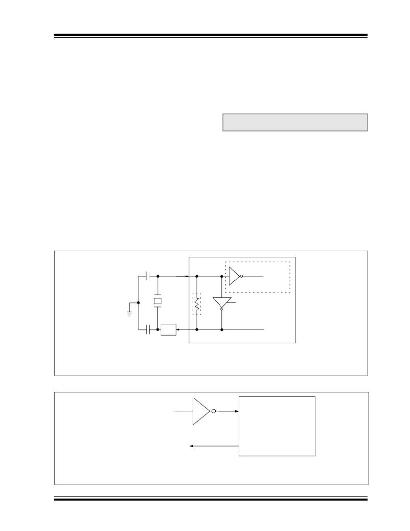
�FIGURE� 8-1:�
�CRYSTAL/CERAMIC� RESONATOR� OPERATION�
�OSC1�
�C� 1�
�To� internal� logic�
�C� 2�
�XTAL�
�R� S� (1)�
�OSC2�
�R� F� (2)�
�Sleep�
�Note� 1:� A� series� resistor� (R� S� )� may� be� required� for� AT� strip-cut� crystals.�
�2:� The� feedback� resistor� (R� F� ),� is� typically� in� the� range� of� 2� to� 10� M� ?� .�
�FIGURE� 8-2:�
�EXTERNAL� CLOCK� SOURCE�
�Clock� from�
�external� system�
�(1)�
�OSC1�
�Open�
�OSC2�
�Note� 1:� A� resistor� to� ground� may� be� used� to� reduce� system� noise.� This� may� increase� system� current.�
�2:� Duty� cycle� restrictions� must� be� observed� (see� Table� 12-1� ).�
�?� 2003-2012� Microchip� Technology� Inc.�
�DS21801G-page� 55�
�发布紧急采购,3分钟左右您将得到回复。
相关PDF资料
MCP3905EV
BOARD DEMO FOR MCP3905
MCP402XEV
BOARD EVAL FOR MCP402X
MCP42XXEV
BOARD EVALUATION MCP42XX
MCP43XXEV
BOARD EVALUATION MCP43XX
MCP46XXDM-PTPLS
BOARD PICTAIL DIGI POT MCP4XXX
MCP46XXEV
EVAL BOARD FOR MCP46XX
MCP4XXXDM-DB
BOARD DAUGHTER DIGIPOT MCP4XXX
MCP6S2XEV
BOARD EVALUATION FOR MCP6S2X
相关代理商/技术参数
MCP2515-E
制造商:MICROCHIP 制造商全称:Microchip Technology 功能描述:Stand-Alone CAN Controller with SPI Interface
MCP2515-E/ML
制造商:Microchip Technology Inc 功能描述:
MCP2515-E/P
功能描述:网络控制器与处理器 IC W/ SPI Inter 125dC RoHS:否 制造商:Micrel 产品:Controller Area Network (CAN) 收发器数量: 数据速率: 电源电流(最大值):595 mA 最大工作温度:+ 85 C 安装风格:SMD/SMT 封装 / 箱体:PBGA-400 封装:Tray
MCP2515-E/SO
功能描述:网络控制器与处理器 IC W/ SPI Inter 125dC RoHS:否 制造商:Micrel 产品:Controller Area Network (CAN) 收发器数量: 数据速率: 电源电流(最大值):595 mA 最大工作温度:+ 85 C 安装风格:SMD/SMT 封装 / 箱体:PBGA-400 封装:Tray
MCP2515-E/SORB4
制造商:Microchip Technology Inc 功能描述:
MCP2515-E/ST
功能描述:网络控制器与处理器 IC W/ SPI Inter 125dC RoHS:否 制造商:Micrel 产品:Controller Area Network (CAN) 收发器数量: 数据速率: 电源电流(最大值):595 mA 最大工作温度:+ 85 C 安装风格:SMD/SMT 封装 / 箱体:PBGA-400 封装:Tray
MCP2515-I
制造商:MICROCHIP 制造商全称:Microchip Technology 功能描述:Stand-Alone CAN Controller with SPI Interface
MCP2515-I/ML
制造商:MICROCHIP 制造商全称:Microchip Technology 功能描述:Stand-Alone CAN Controller with SPI Interface